Most of the seal replacement is a simple procedure. Most of the seals/gaskets are O-rings. Most can be obtained at any good hardware or home center. A Dash number is assigned to each size O-ring. An O-ring chart can be found at the Satori Seal Co. if you need the exact dimension or have a different size O-ring in your Pavoni. You'll need Acrobat Reader installed on your computer to view it. Not every supplier goes by Dash numbers so you will need the exact dimensions when you purchase your O-ring. The chart also has the corresponding metric size. Of course, you won't need this information if you obtain your O-rings from a Pavoni dealer or if you take the O-ring with you to match it up at the supplier. O-rings are found on the following parts:
The other seals comprise of the Group piston gaskets, the mini rubber gasket located internally in the upper part of the Group, and a mini rubber gasket inside the steam knob tee assembly. These are the other seals which you could replace on a yearly basis. If you order these gaskets through a la Pavoni dealer, they generally will sell you individual seals. Some will sell you a replacement pack of all the seals/gaskets you need to rework the Group. The piston seals and the Group components are the most specialized items. You'll probably have to order these from a dealer.
There are seals and gaskets located on the sight glass assembly, and a seal for the heating element. Replacing the sight glass seals is probably the most difficult repair on the machine. The sight glass seal replacement would involve more time than money.
Let's cover seal replacement starting at the top of the machine and working down.
REPLACING THE STEAM KNOB MINI GASKET AND STEAM SHAFT TEE O-RING
Unscrew the 10MM chrome retaining nut. Remove the steam knob assembly by unscrewing it from the machine. This repair is a little difficult since you have to knock the pin out of the steam knob. The knob is made out of Bakelite® which can break easily. Try and find a nail, nail set or other item that will fit the hole, but not so small as to go inside the pin and expand it since the pin is hollow. It has to be a bit smaller than the hole. Put the knob on a protective surface and punch the pin out. I use a nail with the point cut off. Hit the pin until it is half way out. Then use some needle nose pliers to twist the pin out. From here is an easy process to remove the metal washer, take out the old seal, and replace it with the new one. Assemble the shaft back together. Place the shaft back into the knob, and put the pin back in the knob. If the pin doesn't want to stay in the knob, you may have to expand the pin slightly so it stays put. Punching the pin out tends to compress the pin. Screw the assembly back in the machine. Tighten the chrome retaining nut slightly. Don't over tighten!
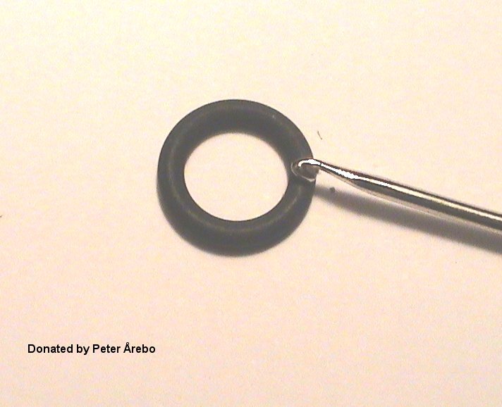
The steam shaft tee O-rings are pretty simple to replace. Just roll them out of the grooves with your fingers or pick them out with some tweezers. Scoring them with an X-ACTO� knife may help in removing them. Be careful not to score the grooves.
REPLACING THE AUTO VALVE, TOP OF AUTO AERATOR, AND TANK KNOB O-RING
This is pretty much common sense. Pull the gasket(s) out of their respective groove(s) and replace them with the new O-ring(s). Using some small tweezers may help in pulling out the old O-ring(s). The majority of the time, you should be able to roll the O-ring out of the groove with just your fingers. If you use an X-ACTO� knife to score the O-ring(s) be very careful not to score the retaining groove(s). A jabbing motion rather than a cutting one will lessen the chance of scoring the groove. You don't have to cut the o-ring completely through to remove it. A cut here and there will weaken the o-ring enough that it will come out more easily. Another option to help remove the O-rings is to use a crochet hook. The end of the hook is rather blunt and would lessen the chance of scoring the seating surface or groove.
REPLACING THE GROUP PISTON GASKETS AND GROUP TO BOILER GASKET
Unscrew the 14MM chrome cap nut and retaining nut that are on top of the Group. If you don't have the correct metric wrench, use an adjustable wrench. I don't like using adjustable wrenches because they tend to round off the corners of the nut or bolt. Take off the chrome c-clips on one side of the lever. Be careful not to scratch the chrome. Use a small piece of wood or even your fingers to slide the c-clips off. Push out the lever inserts (pins) that the c-clips go on. The lever can now come off. There is a small roller that goes into a cavity on top of the Group, that also comes out. Place all of the loose parts together. The piston assembly can now be taken out. This is where you have some difference of opinion of how to remove the piston assembly. I like the method of pushing the piston down until it comes in contact with insert screen. Just grasp the top of the piston rod where the chrome nuts came off and push down until it stops. I now recommend that you remove the Group from the boiler. Older Pavoni's do not bolt the Group on, it's permanently attached to the boiler. If your insert screen O-ring has been installed for a while you may have to hit the piston rod with a little bit of force. You may weaken the solder joint where the boiler flange is attached. With the Group removed you are not taking that chance. If you leave the Group on, fold a towel and hold it on the bottom of the Group and support the Group with your hand while striking the piston rod. If you are taking the Group off, unscrew the two 10MM chrome tank bolts that are on either side of the Group flange. These are metric bolts. Again, you can use an adjustable wrench, but be careful. There is a tube attached to the Group, so when you're ready to take the Group off, drop it down and forward as to not damage the tube. There is an O-ring that you should replace that sits in a groove behind the flange on the Groups that bolt from the outside. Fold a towel and hold it under the Group. While holding the Group in the palm of your hand, take a rubber mallet and give the top of the piston rod a few sharp blows. It may take 3 or more hits until it comes out. If you don't have a rubber mallet hold a piece of wood on top of the piston rod and hit the wood not the piston rod with your hammer. Whatever method you use take care not to damage the siphon tube.You could take an X-Acto� knife and cut the O-ring in the groove that holds the insert screen in place. Making a few cuts around the O-ring will weaken it enough so the insert screen comes out fairly easily. If using a mallet doesn't appeal to you, there is a gentler approach. Turn the Group upside down and grab the gasket with some needle nose pliers. Pull out the gasket,and the insert screen will fall out. Then grab the piston rod and push the piston out of the Group. The gasket will be hard to grasp since it has been compressed by the repeated locking of the coffee filter holder. That's why I choose to hit it out, it's easier to remove. The insert screen won't get damaged if you exert some care in this operation. If you will not be replacing the mini rubber gasket, skip the next paragraph.
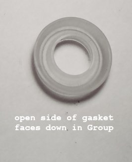
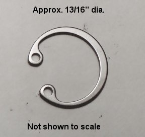
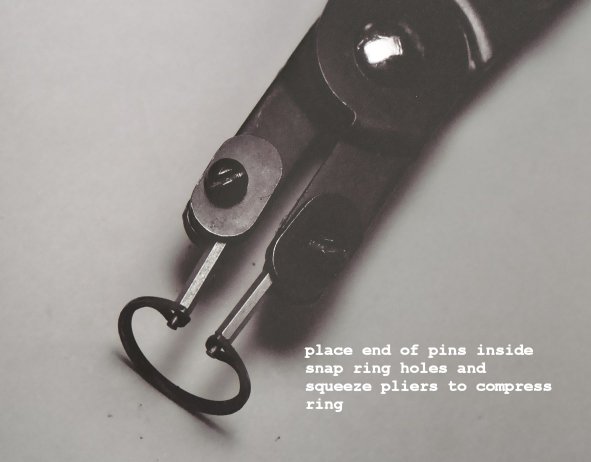
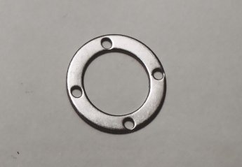
The Group will have to be removed to replace this gasket. The mini gasket is held in place by a retaining clip. It is approx. 13/16" in diameter. A set of internal retaining ring pliers is needed to remove the clip. Any local automotive parts store or Sears store sell this item. The cost is approximately $20. Put the appropriate pins (.060) in the pliers, squeeze the clip, and remove it from the groove. You can use larger tips if you have them. My set had different size tips,.060 was the largest.The holes in the clip are 1/16" in diameter.There is also a brass retainer ring that needs to be removed. Nothing is holding it in place. You could use the retaining ring pliers or tweezers to grab onto it. Pull it off of the mini rubber gasket. After the brass retaining ring is out, take some needle nose pliers and pull out the gasket. Smear some lubricant on the surface of the new gasket where the piston rod will travel. Put the new gasket in making sure that the groove in the gasket will face downward as if the machine were in the upright position. Make sure the new gasket is firmly seated. Drop the brass retaining ring in, and put the c-clip back in to the groove using the c-clip pliers. The c-clip must seat into the groove. If you don't push the mini rubber gasket down far enough, it will prevent you from installing the c-clip. Now, you're ready to put the new piston gaskets on.
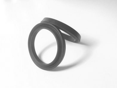
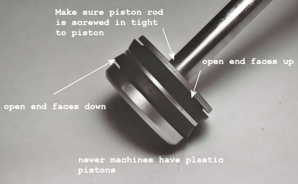
The piston gaskets are somewhat hard to take off and install. Gently cut the old gaskets with an X-Acto� knife while pulling it out of the groove with needle nose pliers, making sure not to cut into the brass/plastic piston. After cutting through the gaskets, take some needle nose pliers and pull the gaskets out of their grooves. Place the new gaskets in very hot water for a minute, and then slide them over the piston and seat them in the grooves. The open side of the gaskets will face upward on the top groove and face downward in the bottom groove. One word on installing the gaskets. Place one part of the gasket into the piston groove. Hold the gasket in the groove with your thumb. Gradually work the the rest of gasket into the groove while using your other fingers to keep all of the gasket in the groove. The gasket wants to flip itself so the groove of the gasket is not facing in the correct position. It wants to face outward. You can use some U.S.D.A. approved lubricant, (H1) for incidental food contact, to help in the assembly. Lightly coat the piston to help get the gaskets in their grooves. It is used only for assembly purposes. Don't use ball bearing grease! (:}) Don't over apply the lubricant. Put it on so you can't even see it. The hot water and steam are really what lubricates the piston seals during operation. Any lubricant you use will dissipate after a short while. Before you insert the piston assembly, twist the piston rod where it goes into the piston head, making sure it is tight. Lightly coat the piston rod with lubricant. Now slide the piston into the Group and push it all the way up into the Group. I also coat the inside piston wall to help in this operation. Place the insert screen in the Group and put a O-ring around the insert screen. I use half of a wooden clothespin to push the O-ring down around the screen, making sure it is firmly seated in the groove. Insert a new O-ring in the groove of the flange and attach the Group back onto the tank and equally tighten the tank mounting bolts. Don't over tighten these bolts! They don't have to be torqued down. Now, reassemble the handle, roller, pins and c-clips onto the Group. Be careful not to put the handle upside down. The front hole that goes through the piston rod is drilled lower on the yoke than the back hole. Remember to slide the back pin through the roller when reassembling the handle. The front pin should go through the handle and also through the piston rod hole. Screw the chrome retaining nut all the way down on the piston shaft, then screw on the chrome cap nut. The piston should travel very easily in the Group.
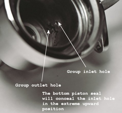
NOTE: The lower piston gasket will cover the inlet hole to the Group when the piston is in the extreme upward position. One would logically think that the piston would travel past the hole as to let water enter the Group. Since the gasket is covering the inlet hole the water has to force itself between the Group wall and gasket. You will notice the flow of water out of the Group does not look like a shower head spray on newly installed piston gaskets. I imagine this is due to the new gasket being more firm than the old gasket thus giving more resistance to the water entering the Group. The flow of water out of the Group will look more like a shower head spray once the gasket weakens. It doesn't seem logical at first why it was engineered this way but I assume Pavoni did it so the force of the water would be diffused. The water would trickle more into the Group than come in at full force. This way the tamping of the grounds would not be disturbed. This explanation is pure conjucture on my part. NOTE: On the newer machines there are no inlet/outlet holes in the wall of the Group. Water enters and leaves the Group through the plastic flange in the back of the Group.
REPLACING THE SIGHT GLASS GASKETS
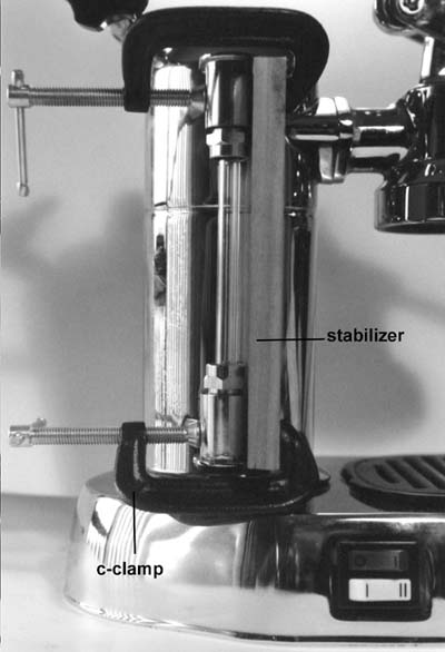
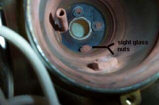
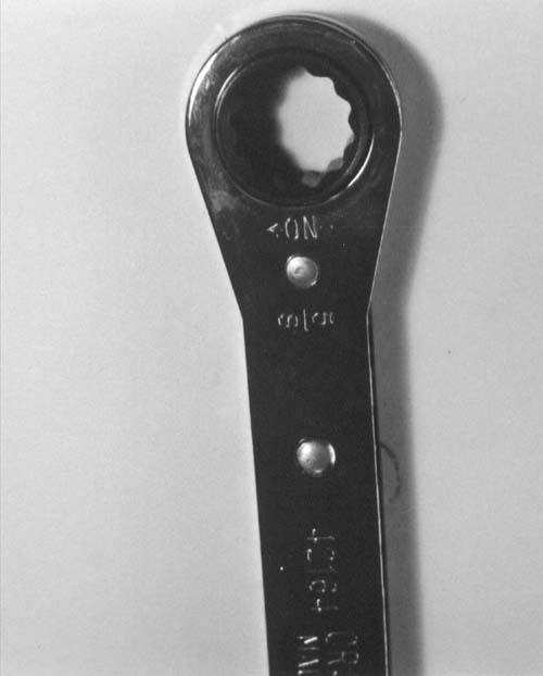
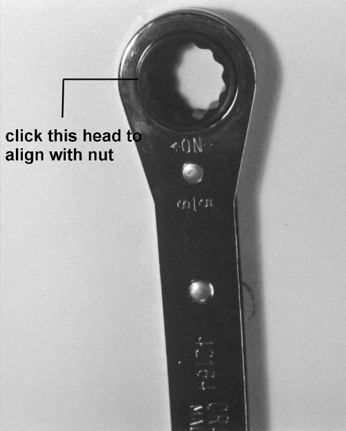
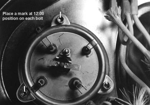
This is the hardest repair to the machine. The main thing to remember is to isolate the top and bottom sight glass fittings from turning. If you don't, you risk breaking the sight glass tube, since the fittings will turn as you loosen or tighten the nut from inside the boiler. This also keeps the sight glass fittings in proper alignment. To keep the fittings from turning, I clamped a small piece of wood between the two fittings. I used a piece of wood 1/2 x 2 x 6 1/4 for the stabilizer. I wouldn't want to go thinner than 1/2". Be careful not to tighten the c-clamps too tight. You don't want to crack a fitting. I removed the plastic sight glass shield so I wouldn't crack it with the c-clamps. The shield is a little hard to remove since it has two tabs that fit inside recesses in the fittings. One recess in the top and one in the bottom opposite each other. Once you pry the tabs out, the shield slides right off the fittings. After you isolate the fittings, you can start to take the assembly off the machine. First, remove the base of the machine. Next, remove the wiring from the heating element. Make a simple wiring diagram so that when you reinstall the element, you can hook up all the wiring correctly. Note the relationship of the heating element to the brass retaining ring. Take a felt pen and place a mark on the element and on the retaining ring opposite each other. This way, the element will be in the original position when you reinstall it. Loosen the three bolts that hold the element in place. After the element is removed, you can now access the boiler. The nuts inside my boiler are 16MM. If you don't have a 16MM wrench, a standard 5/8" is acceptable. Actually, the 5/8" is a better fit. The bottom nut is very easy to loosen. The upper nut is the hardest to access. The best tool to use on these nuts is a 5/8" 12 point self ratcheting box wrench. Remember even with this, there is a little trick to get the nut on or off. One side of that is, you don't have much room to work the wrench around the nut. Remember one side of the self ratcheting wrench loosens and the opposite side tightens the nut. It's marked in the wrench on or off. Here comes the advantage of the self ratcheting wrench. When you initially put the wrench inside the boiler, you may or may not succeed in getting the wrench around the nut. If you can, simply turn the wrench counterclockwise till it hits the side of the boiler. If you can't get the wrench around the nut ,pull the wrench out of the boiler and manually click the head about two clicks. This will orient the wrench to the points on the nut. Now try again to loosen the nut. You may have to do this procedure multiple times to get the nut off! Or, if you are lucky, once you get the nut loosened a little, you may be able to spin it off with your fingers. There is a washer between the boiler and the nut. Don't lose it. It may be stuck to the nut. I also put my thumb down the top of the boiler to help guide and hold the wrench on the nut.
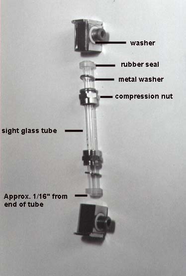
Remove the assembly from the machine and take off the c-clamps. The two compression nuts on the sight glass are 17MM. Loosen the two compression nuts and remove the tube from the fittings. If the tube doesn't want to come out, soak the assembly is some vinegar and hot water. After you get the tube out, remove the brass washer and rubber seal from each fitting. Clean the fittings and sight glass tube. After cleaning, put the two compression nuts on the tube. Make sure that the threaded portion faces out on both nuts. Place the brass washers on next, then the two rubber seals. I left about 1/16" of the tube showing on both ends. Insert one end of the tube into a fitting, making sure everything is seated correctly. Hand tighten the compression nut. Assemble the other end of the tube the same way. Final tightening of the compression nuts to be done later! Place the plastic washers on each nipple of the fittings. There is a recess in each fitting for the washer. Now is the time to put the assembly on the boiler. Make sure the top fitting faces up. This is the fitting that has a spot for a pressure gauge. Insert each nipple of the assembly through the holes in the boiler. If the nipples don't line up with the holes in the boiler, take the assembly off the machine. Reposition the seals on the tube either higher or lower on the tube. This will enlongate or shorten the assembly. Once the assembly is fitted in the holes, install the washer and nut on each fitting. Hand tighten only! Isolate the fittings again, with your wood and c-clamps. Make sure the edge of the wood is not past the fitting next to the boiler. You want the fittings to be drawn next to the boiler without any interference. Alternate tightening the upper and lower nut. Don't torque these nuts down. Just snug them up. You can always tighten them if you have a leak. Remove your wood and c-clamps. Install the plastic shield, aligning the tabs inside the shield to the recesses on the fittings.
Take out the old gasket from the heating element. Install a new gasket in the element, no sealant necessary. Place the element in the original position and hand tighten the three bolts that hold it on the brass retainer ring. I use a felt tip pen and place a mark on the head of each bolt at the 12:00 position. This way when I start to tighten the bolts, I know that they are being evenly tightened. Tighten each bolt a little bit in an alternating fashion. Hold the element in place firmly and evenly when tightening the bolts. I tightened the bolts about 3/4 of a turn. After the element is installed, put a little cold water in the boiler. Check for leaks. If there are no leaks when it's cold, cap the boiler, reconnect all of the electrical wiring and turn on the machine. I kept the bottom off and elevated the machine so I could test for leaks with a mirror on the hot test. Remember, that machine gets very hot. Exercise some caution on the hot test. Bring it up to operating pressure. If no leaks, put the base back on. If you have leaks determine where it is leaking and fix the problem. If you have to retighten nuts, do it a little a time. Don't overdo it. Unfortunately, if one of the sight glass fittings leak, you'll have to remove the heating element and tighten the nuts as in the above procedure. I've tried to work from the top of the boiler for this repair, but it didn't work for me. It's hard to work a wrench in that small of a diameter hole. Make yourself an espresso you deserve it!
Note: I had to add this comment since I have received a lot of suggestions that the above procedure is too involved. That there is an easier way to replace the seals on the sight glass. It's true that if you remove the screw on the top fitting, the sight glass tube can be pushed up through that hole and you can replace the seals that way. I have some problems with that suggestion. First, the sight glass tube is fragile and I have had people write and tell me they broke the tube trying to remove it from the top fitting. Second, my procedure is a 100% replacement of all seals. There are two gaskets that go between the boiler and sight glass fittings. I think my method is almost 100% mistake proof and I'm satisfied that it is the better way to go. A lot of times it takes a bit longer to do a good job than looking for an easy fix. Not that I'm against doing a job easier, as long as you get the same results. So if you want to go that way, go ahead. Remember, if you break that tube your Pavoni will be down for a couple of weeks waiting on that replacement tube. I'm not trying to discourage anyone from sending me suggestions on how to fix the Pavoni. If you have a better idea let me know and I'll change the instructions if I agree with your method. Hey, it's my web site!
REPLACING THE HEATING ELEMENT OR HEAT ELEMENT GASKET
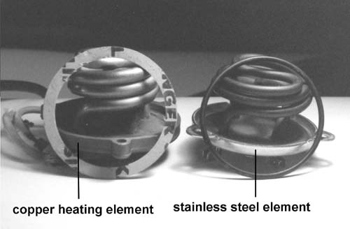
Make sure you order the correct gasket for your element. The copper element has a flat gasket and the stainless steel element has a round rubber gasket. If you have a copper element and it is bad, you'll probably have to order a stainless steel element. I've been told that Pavoni discontinued making the copper element. This is not all bad since you have to retrofit to a resettable fuse. It costs a little more but it is highly advisable. The regular fuses were a little expensive. When you figure what element or gasket you need, it's a pretty simple procedure to remove the element from the boiler. Unplug the machine and empty the water from the boiler. Remove the base of the machine. Make a simple wiring diagram so you can hook the wires back up correctly. Note the relationship of the heating element to the brass retaining ring (flange). Take a felt pen and place a mark on the element and on the brass retaining ring (flange) opposite each other. This way, the element will be in the original position when you reinstall it. If you had to go to a stainless steel element, the terminals on the element may be orientated differently than the copper element. If you are replacing with a new element, you may need your multi-tester to identify the high & low heat terminals on the new element. After you make up your diagram, unplug the wiring from the element. Depending on what kind of bolt is holding the element on, obtain the wrench or allen screw and unscrew the three bolts. The element will fall right out. Clean the bottom of the boiler where the gasket will come in contact. Remove the old gasket and clean the seating surface and install the new gasket in the element recess. Place the element in the boiler and try to get it as close to the original element position as possible. If you are reinstalling the original element just line up the felt pen marks. Screw in your three bolts while holding the element firmly and evenly to the bottom of the boiler. Handtighten only. Place a mark on each bolt at the 12:00 position with a felt pen. I do this so I know exactly how much I have tightened each bolt. Tighten each bolt a little at a time in an alternating fashion. I tightened my bolts approx. 3/4 of a turn. Don't overtighten these bolts. Fill the boiler a little with cold water and check for leaks. If no leaks, attach all of the wiring and fill the boiler up. Cap the boiler, plug the machine in and bring it up to operating pressure. Check for leaks. If you have leaks, find the spot and correct it. It may take just a little more tightening of a bolt. You don't have to torque any of these bolts down. Tighten a little at a time to correct a leak. I kept the bottom off and elevated the machine so I could test for leaks with a mirror on the hot test. Remember, that machine gets very hot. Exercise some caution on the hot test. If no leaks, install the bottom and you're ready to go.
Click on link to view